[Stee Design] JOINT DETAILING OF STEEL HOLLOW SECTIONS.

[Stee Design] JOINT DETAILING OF STEEL HOLLOW SECTIONS.

*JOINT DETAILING OF STEEL HOLLOW SECTIONS*

Detailing of joints in steel structure is as much important as detailing of main structural members. Ultimately loads from structures are transferred to different structural members through joints. So, a good detailing of joints in steel structure is required to make the structure safe for the given loads.

Here we will discuss about the types of joints commonly used for structural steel hollow sections. Hollow sections are of three types, Rectangular Hollow Sections (RHS) and Square Hollow Sections (SHS) and Circular Hollow Sections (CHS).

Following are the joint details for structural steel hollow sections (RHS and SHS) commonly used:

1. K – Type Joints:

K – Type joints in steel structures are formed when the centroidal axis of horizontal member and two lateral bracings meet with the central axis of top chord. Following figure shows K-Type joint:

It should be ensured that the ends of hollow sections are always closed. If any ends of a hollow section does not get closed due to more width, then a plate is welded on that end so that the ends gets closed and also the connection with other members are made good by effective sealing of the members. This also prevents internal corrosion of the hollow sections.

K-type of joints in structural steel members is simplest and most economical.

2. Knee – Type Joint:

To increase the stability of connection between vertical and horizontal members of structure, knee-type joint is used.

In welded knee-joint, the top chord is directly welded to the main column and then a suitably cut haunch is welded to the vertical and as well as to the chord member for better stiffening. The knee-type joint is shown below:

3. N – Type Joint:

N-type joint is formed as per the adopted configuration, for connecting web members to top and bottom chords. Typical details of one of the joints are given below:

i) In this joint, first the vertical member is put in place and directly welded to top and bottom chords.

ii) Afterwards, the other inclined diagonal member, with suitable double cuts at the ends, is directly welded to top and bottom chords and also to the vertical.

iii) These connections, of vertical and diagonal members to top and bottom chords directly, help in eliminating the gusset plates thus resulting in automatic sealing of member ends. Direct jointing, of vertical and diagonal members to top and bottom chords, eliminates gusset plates.

4. Gap Joint:

When two smaller sections are to be joined with a bigger section, a gap between two smaller sections remains. When the intersection of centroidal axes of two smaller size members lies in the centroidal axis of larger size member i.e. bottom boom of landing, this type of joint is formed.

5. Overlap Joint:

This type of joint is used in elevation for connecting three smaller size members so that two members are in close touch with each other and also the intersection of their centroidal axes lies on the axis of third member.

6. Vierendeel Joint:

In this type of joint the vertical member is directly welded to the top chord by fillet weld. Following figure shows typical details of Vierendeel Joints between hollow sections:

In this type of Vierendeel joint the width of the vertical member is less than the chord members. This is a most suitable joint.

Read More

Permeable Pavement System In Pavement Construction.

Permeable Pavement System In Pavement Construction.

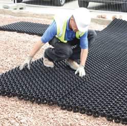
Permeable pavement system

Permeable paving is a range of sustainable materials and techniques for permeable pavements with a base and sub base that allow the movement of storm water through the surface.
In addition to reducing runoff, this effectively traps suspended solids and filters pollutants from the water. Examples include roads, paths, lawns and lots that are subject to light vehicular traffic, such as car/parking lots, cycle-paths, service or emergency access lanes, road and airport shoulders, and residential sidewalks and driveways.
Although some porous paving materials appear nearly indistinguishable from nonporous materials, their environmental effects are qualitatively different. Whether previous concrete, porous asphalt, paving stones or concrete or plastic-based pavers, all these previous materials allow storm water to percolate and infiltrate the surface areas, traditionally impervious to the soil below.
The goal is to control storm water at the source, reduce runoff and improve water quality by filtering pollutants in the substrata layers.

Read More

[RCC] Types Of Post Tension Methods.

[RCC] Types Of Post Tension Methods.

TYPES OF POST TENSION METHODS -

1. Freyssinet System:

Freyssinet system was introduced by the French Engineer Freyssinet and it was the first method to be introduced. High strength steel wires of 5mm or 7mm diameter, numbering 8 or 12 or 16 or 24 are grouped into a cable with a helical spring inside. Spring keeps proper spacing for the wire. Cable is inserted in the duct.

Anchorage device consists of a concrete cylinder with a concentric conical hole and corrugations on its surface, and a conical plug carrying grooves on its surface (Fig. 3). Steel wires are carried along these grooves at the ends. Concrete cylinder is heavily reinforced. Members are fabricated with the cylinder placed in position. Wires are pulled by Freyssinet double acting jacks which can pull through suitable grooves all the wires in the cable at a time. One end of the wires is anchored and the other end is pulled till the wires are stretched to the required length. An inner piston in the jack then pushes the plug into the cylinder to grip the wires.

2. Magnel Blaton system:

In Freyssinet system several wires are stretched at a time. In Magnel Blaton system, two wires are stretched at a time. This method was introduced by a famous engineer, Prof. Magnel of Belgium. In this system, the anchorage device consists of sandwich plate having grooves to hold the wires and wedges which are also grooved. Each plate carries eight wires. Between the two ends the spacing of the wires is maintained by spacers. Wires of 5mm or 7mm are adopted. Cables consists of wires in multiples of 8 wires. Cables with as much as 64 wires are also used under special conditions. A specially deviced jack pulls two wires at a time and anchors them. The wires with the sandwich plate using tapered wedge.

3. Gifford Udall System:

This system originated in Great Britain, is widely used in India. This is a single wire system. Each wire is stressed independently using a double acting jack. Any number of wires can be grouped together to form a cable in this system. There are two types of anchorage device in this system.

a) Tube anchorages

b) Plate anchorages

Tube anchorage consists of a bearing plate, anchor wedges and anchor grips. Anchor plate may be square or circular and have 8 or 12 tapered holes to accommodate the individual prestressing wires. These wires are locked into the tapered holes by means of anchor wedges. In addition, grout entry hole is also provided in the bearing plate for grouting. Anchor wedges are split cone wedges carrying serrations on its flat surface. There is a tube unit which is a fabricated steel component incorporating a thrust plate, a steel tube with a surrounding helix. This unit is attached to the end shutters and form an efficient cast-in component of the Anchorage.

4. Lee McCall System:

This method is used to prestress steel bars. The diameter of the bar is between 12 and 28mm. bars provided with threads at the ends are inserted in the performed ducts. After stretching the bars to the required length, they are tightened using nuts against bearing plates provided at the end sections of the member

5. Other Methods of Prestressing:

a) Electrical Prestressing:

in this method, reinforcing bars is coated with thermoplastic material such as sulphur or low melting alloy and buried in the concrete. After the concrete is set, electric current of low voltage but high amperage is passed through the bar. Electric current heats the bar and the bar elongates. Bars provided with threads at the other end are tightened against heavy washers, after required elongation is obtained. When the bar cools, prestress develops and the bond is restored by resolidification of the coating.

b) Chemical Prestressing:

Chemical prestressing is done using expanding cement. Prestressing can be applied b embedding steel in  concrete made of expanding cement. Steel is elongated by the expansion of the concrete and thus gets prestressed. Steel in turn produces compressive stress in concrete.

Read More